Introduction
All digital computers are built with the basic components shown on this page.
All other circuits, including the
Xor Gate shown below, can be constructed
with Inverter Gates,
Or Gates, and And Gates.
What makes computers so complicated is that they are composed of millions of
these basic gates, interconnected in very intricate ways.
When you have finished studying these concepts, you can
cement your comprehension with a companion page,
Digital Logic Primer Exam,
an on-line, interactive test of this material.
Contents
Definitions
As you study this page, here are some things to consider:
- A State is a way of being..
- An Input is a pin, connection, or electrical signal that goes INTO
a device that affects its current state in some way.
- An Output is a pin, connection, or electrical signal that comes
OUT of a device and reflects its current state.
- For Binary Digital Computers:
| Binary States
|
|---|
| Inputs and Outputs | Off | On
|
|---|
| 0 | 1
|
|---|
| False | True
|
|---|
| Switches on this page | Down | Up
|
|---|
|
|
|
| LED's on this page | Dark | Lit
|
|---|
|
|
|
- In general, Outputs are connected to Inputs.
- The Switches are Input Devices. On this page, all switches have
ONE OUTPUT. which can be connected to ONE OR MANY INPUTS
- The LED's are Output Devices. On this page, all LED's have
ONE INPUT which can be connected to just ONE OUTPUT.
- All Logic Gates on this page have either ONE or
TWO or THREE INPUTS, with only ONE OUTPUT.
- A Truth Table is a list of all the possible input states
of a device along with the resulting output states.
You are invited to experiment with the switches on this page. Clicking them
will change their state -- that is, from a "Down / 0" to a
"Up / 1", and vise versa. Then watch what happens to the LED's in the same box.
The circuits below are the most basic found in a
Binary Digital Computer.
| Basic Circuits |
|---|
| Name | Schematic Symbol | Truth Table | Description |
|---|
| Switch and LED |
|
| Switch | LED |
|---|
| Down / 0 | Dark / 0 |
| Up / 1 | Lit / 1 |
|
The most basic of all circuits. The switch on the left will
turn the LED (Light Emitting Diode) on the right on. Click it and see.
|
|---|
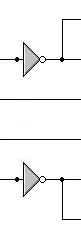
| Inverter Gate |
|
| Switch | LED |
|---|
| 0 | Lit / 1 |
| 1 | Dark / 0 |
|
The most basic gate. It changes its input from a "1" to a "0", and
vise versa.
|
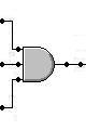
| And Gate |
|
| Switches | LED |
|---|
| 0 | 0 | Dark / 0 |
| 0 | 1 | Dark / 0 |
| 1 | 0 | Dark / 0 |
| 1 | 1 | Lit / 1 |
|
This gate will output a "1" only if both its inputs are a
"1"
|
.
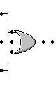
| Or Gate
|
|
| Switches | LED |
|---|
| 0 | 0 | Dark / 0 |
| 0 | 1 | Lit / 1 |
| 1 | 0 | Lit / 1 |
| 1 | 1 | Lit / 1 |
|
The output of this gate is a "1" if either of its inputs
is a "1"
|
|---|
The circuits below are built out of the
Basic Circuits shown above.
| Combinational Gates |
|---|
| Name | Schematic Symbol | Truth Table | Description |
|---|
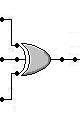
| Xor Gate |
|
| Switches | LED |
|---|
| 0 | 0 | Dark / 0 |
| 0 | 1 | Lit / 1 |
| 1 | 0 | Lit / 1 |
| 1 | 1 | Dark / 0 |
|
Xor is short for Exclusive Or.
This gate can be implemented with
Inverter Gates,
And Gates,
and Or Gates (See below).
The output of this gate is a "1" only if one of its inputs
is a "1"
|
| Xor Circuit |
|
|---|
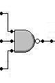
| Nand Gate |
|
| Switches | LED |
|---|
| 0 | 0 | Lit / 1 |
| 0 | 1 | Lit / 1 |
| 1 | 0 | Lit / 1 |
| 1 | 1 | Dark / 0 |
|
Nand is ahort for Negative And.
This gate combines an And Gate with its output connected
through an Inverter Gate in one device.
It will output a "0" only if both its inputs are a "1"
|
.
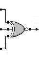
| Nor Gate |
|
| Switches | LED |
|---|
| 0 | 0 | Lit / 1 |
| 0 | 1 | Dark / 0 |
| 1 | 0 | Dark / 0 |
| 1 | 1 | Dark / 0 |
|
Nor is short for Negative Or.
This gate combines an Or Gate with its output connected through an
Inverter Gate in one device.
It will output a "0" if either its inputs are a "1"
|
.
| Xnor Gate |
|
| Switches | LED |
|---|
| 0 | 0 | Lit / 1 |
| 0 | 1 | Dark / 0 |
| 1 | 0 | Dark / 0 |
| 1 | 1 | Lit / 1 |
|
Xnor is short for Exclusive Nor.
This gate combines an Xor Gate
with its output connected through an
Inverter Gate in one device.
The output of this gate is a "0" only if one of its inputs
is a "1"
|
The circuits below are built out of the
Basic Circuits shown above.
| Triple Input Gates |
|---|
| Name | Schematic Symbol | Truth Table | Description |
|---|
| 3-Input And Gate |
|
| Switches | LED |
|---|
| 0 | 0 | 0 | Dark / 0 |
| 0 | 0 | 1 | Dark / 0 |
| 0 | 1 | 0 | Dark / 0 |
| 0 | 1 | 1 | Dark / 0 |
| 1 | 0 | 0 | Dark / 0 |
| 1 | 0 | 1 | Dark / 0 |
| 1 | 1 | 0 | Dark / 0 |
| 1 | 1 | 1 | Lit / 1 |
|
This gate will output a "1" only if all of its inputs are a
"1"
|
.
| 3-Input Or Gate |
|
| Switches | LED |
|---|
| 0 | 0 | 0 | Dark / 0 |
| 0 | 0 | 1 | Lit / 1 |
| 0 | 1 | 0 | Lit / 1 |
| 0 | 1 | 1 | Lit / 1 |
| 1 | 0 | 0 | Lit / 1 |
| 1 | 0 | 1 | Lit / 1 |
| 1 | 1 | 0 | Lit / 1 |
| 1 | 1 | 1 | Lit / 1 |
|
This gate will output a "1" if any of its inputs are a
"1"
|
.
| 3-Input Xor Gate |
|
| Switches | LED |
|---|
| 0 | 0 | 0 | Dark / 0 |
| 0 | 0 | 1 | Lit / 1 |
| 0 | 1 | 0 | Lit / 1 |
| 0 | 1 | 1 | Dark / 0 |
| 1 | 0 | 0 | Lit / 1 |
| 1 | 0 | 1 | Dark / 0 |
| 1 | 1 | 0 | Dark / 0 |
| 1 | 1 | 1 | Lit / 1 |
|
Xor is short for Exclusive Or.
This gate will output a "1" if only one or all
of its inputs are a "1"
|
.
The circuits below are built out of the
Tripple Input Gates shown above.
| Negative Triple Input Gates |
|---|
| Name | Schematic Symbol | Truth Table | Description |
|---|
| 3-Input Nand Gate |
|
| Switches | LED |
|---|
| 0 | 0 | 0 | Lit / 1 |
| 0 | 0 | 1 | Lit / 1 |
| 0 | 1 | 0 | Lit / 1 |
| 0 | 1 | 1 | Lit / 1 |
| 1 | 0 | 0 | Lit / 1 |
| 1 | 0 | 1 | Lit / 1 |
| 1 | 1 | 0 | Lit / 1 |
| 1 | 1 | 1 | Dark / 0 |
|
This gate will output a "0" only if all of its inputs are a
"1"
|
.
| 3-Input Nor Gate |
|
| Switches | LED |
|---|
| 0 | 0 | 0 | Lit / 1 |
| 0 | 0 | 1 | Dark / 0 |
| 0 | 1 | 0 | Dark / 0 |
| 0 | 1 | 1 | Dark / 0 |
| 1 | 0 | 0 | Dark / 0 |
| 1 | 0 | 1 | Dark / 0 |
| 1 | 1 | 0 | Dark / 0 |
| 1 | 1 | 1 | Dark / 0 |
|
This gate will output a "0" if any of its inputs are a
"1"
|
.
| 3-Input Xnor Gate |
|
| Switches | LED |
|---|
| 0 | 0 | 0 | Lit / 1 |
| 0 | 0 | 1 | Dark / 0 |
| 0 | 1 | 0 | Dark / 0 |
| 0 | 1 | 1 | Lit / 1 |
| 1 | 0 | 0 | Dark / 0 |
| 1 | 0 | 1 | Lit / 1 |
| 1 | 1 | 0 | Lit / 1 |
| 1 | 1 | 1 | Dark / 0 |
|
Xnor is short for Exclusive Nor.
This gate will output a "0" if only one or all
of its inputs are a "1"
|
.
Examination Link
Now that you have familiarized yourself with these concepts, you can
cement your comprehension with a companion page, Digital Logic Primer Exam,
an on-line, interactive test of this material.
More Detail Link
Here is a link to a much more thorough treatment of logic gates and other more complex
devices:
http://www.play-hookey.com/digital/
Credits
These gates, plus many other devices, are part of a software package called
Multimedia Logic,
a free program which simulates digital logic circuits.
It will run under Microsoft Windows '95 and up.
| Visitor #
|
|---|
|
This primer has been written and distributed by
James Larson
Programmer/Analyst Consultant
http://www.dst-corp.com/james
E-mail address
In God We Trust...