IBM PC Parallel Port Interface

for General Electric model PTR 61c Paper Tape Reader

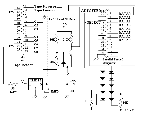
The data output swing from 0V to -12V and the tape motion pulses must be negative going. This circuit will shift these signals for the IBM PC Parallel Port. The transistor can be any general purpose switch such as the 2N2222 and the diodes are standard signal types.

Level Shifters for IBM PC Parallel Interface

IBM PC Parallel Port
I/O Address Bit Number Name ( I )nput / (O)utput DB-25 Pin Number
LPTbase+0 0 DATA0 I/O 2
1 DATA1 I/O 3
2 DATA2 I/O 4
3 DATA3 I/O 5
4 DATA4 I/O 6
5 DATA5 I/O 7
6 DATA6 I/O 8
7 DATA7 I/O 9
LPTbase+1 3 INPUT0
~Error/Fault
I 15
4 INPUT1
SLCT (Online)
I 13
5 INPUT2
Paper Out
I 12
6 INPUT3
~Acknowledge
I 10
7 ~BUSY I 11
LPTbase+2 0 ~STROBE I/O 1
1 ~AUTOFEED O 14 (Blue/Violet)
2 RESET O 16
3 ~SELECT O 17 (Yellow)
5 Data Direction Control for LPTbase+0 Register
0=Output 1=Input
Signal Ground 18, 19, 20, 21, 22, 23, 24 and 25

LPTbase I/O Address Printer Port
0x378 LPT1
0x278 LPT2


Visitor #
This circuit design brought to you by

James Larson
Programmer/Analyst Consultant
http://www.dst-corp.com/james
E-mail address
In God We Trust...